Introduction:
Disc Springs are conically formed angular Discs, which are loaded in the axial direction. Disc Springs offer a well-developed solution to many engineering problems. Through a unique combination of high force in a small space, Disc Springs can be used as single disc or arranged in stacks. A spring stack can consist of either single spring or parallel spring sets. Disc Springs are available with or without contact flats. Disc Springs and Belleville Washers are manufactured to DIN 2093 AND din 6796. We have computerized design programmed to assist our customers for their specified applications. Disc Springs are manufactured from imported 50CrV4 material. Our Disc Springs are AUSTEMPERED. This method of heat treatment is particularly effective for springs, as it gives the maximum toughness and therefore considerable durability.
Advantages of Disc Springs
| 1. | No Deformation or Fatigue under normal loads. |
| 2. | High Energy Storage Capacity. |
| 3. | Long Service Life. |
| 4. | Stock keeping is minimized as the individual spring sizes can be combined universally. |
| 5. | Space Saving. |
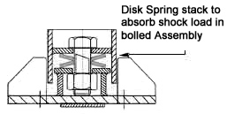
| 6. | Largely Self-damping, giving good shock absorption and energy dissipation. |
| 7. | Efficient use of space and high spring force with small deflections. |
| 8. | Adaptable to stacking in numerous configurations. |
| 9. | Combination use as a modular spring element. |
| 10. | Low Maintenance cost |
| 11 | Greater Security | | |
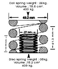
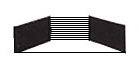
Disc Spring Stack Compared to Helical Spring. |
| Note that the same load is achieved at substantial reduction in space. Disc stacks may be designed for extremely high loads where coil springs are not feasible at all. |
|
| Disc Spring in Series & Parallel Combinations |
Disc Spring in Series & Parallel Combinations
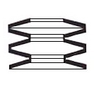 | Disc Spring in Series & Parallel Combinations
 |
|
|
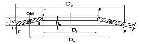
DISC SPRING : SYMBOLS & UNITS
Group Classification of Disc springs |
| In accordance with DIN 2093 Standard, Disc Springs are classified into 3 groups as given in the table: | Symbols and Units |
|
| Group | Thickness of
single disc
in mm | Single disc with Ground ends & reduced material
thickness (t') |
| 1 | less than 1.25 | No |
| 2 | From 1.25 to 6 | No |
| 3 | Over 6 upto 14 | Yes |
|
|
|
| Symbol | Unit | Term |
| De | mm | Outside diameter |
| Di | mm | Inside diameter |
| Do | mm | Mean diameter |
| E | N/mm2 | Modulus of elasticity |
| F | N | Spring load of a single disc
(with or without front ends) |
| ho | mm | Formed height |
| lo | mm | Free overall height of spring in its initial position |
| s | mm | Deflection of single disc |
| t | mm | Thickness of single disc |
| t1 | mm | Reduced thickness of single disc in the case of springs with ground ends (group 3) |
| � | | Poisson's ratio |
δOM,ol,oil,
δIII, &δIV, | N/mm2 | Design stresses at the points designated OM, I, II, III, and IV
(see figure) |
| ▲F | N | Relaxation |
|
|
|
DISC SPRING MATERIALS
Springs in accordance with this standard shall be made from high-grade steel with a modulus of elasticity, �E� of 206,000N/mm2 as specified in either DIN 17221 or DIN 17222, it being noted that CK steel shall be used for the manufacture of group 1 springs only.
IIS can manufacturer Disc Springs from all the above materials. If one requires any other material, we can also use any material as per the customer�s requirement. IIS has in-house chemical and physical laboratory and so all the material is tested in-house before manufacturing. This ensures the quality of the Springs.
Deciding material is a crucial for a spring designer.A List of material used by us to manufacturer springs is available here
It is difficult to derive the amount of material required to be used in a spring based on the load vs. defl-ection requirement. Since Deflection is directly proportional to load, the amt. of material required to changes accordingly. Different materials have different tensile strengths, which are used in initial design calculations. The table below shows the approximate tensile strengths. |
List of Standard Materials for Disc Springs
| ABBREVIATED | MATERIAL | | INTERNATIONAL STANDARD |
| NAME | NO. | DIN | FRANCE AFNOR | BRITAIN B.S. | AISI | USA SAE | ASTM |
| Ck 67 | 1.1231 | 17 222 | XC 68 | 060 A 67 | 1070 | - | - |
| Ck 75 | 1.1248 | 17 222 | XC 75 | 060 A 68 | 1080 | 1078 | - |
| 50 Crv 4 | 1.8159 | 17 222 | 50 CV 4 | 735 A 50 | 6150 | - | - |
| 51 CrMo V 4 | 1.7701 | 17 221 | 51 CDV 4 | - | - | - | - |
| 48 CrMoV 67 | 1.2323 | 17 350 | - | - | - | - | - |
| X 30 WCrV 53 | 1.2567 | - | Z 32 WCV 5 | - | - | - | - |
| X 22 CrMo 12 1 | 1.4923 | 17 240 | - | - | - | - | - |
| X 7 CrNiAl 17 7 | 1.4568 | 17 224 | - | - | - | - | - |
| X 12 CrNi 17 7 | 1.431 | 17 224 | Z 8 CAN 17.07 | - | 631 - -
AMS 5528, 5529, 5673 |
| X 5 CrNiMo 17 12 2 | 1.4401 | 17 224 | Z 12 CN 17.07 | 301 S 21 | 301 | | |
| NiCr 19 NbMo (Inconel 718) | 2.4668 | 65 021 | Z 6 CND 17.11 | 316S 16, 316 S 31 | 316 | 30316 | A 182 |
| NiCr15 Fe 7 TiAl (Inconel X 750) | 2.4669 | - | NC 19 FeNb | HR 8 | AMS 5596 D |
| NiCr 20 Co 18 Ti (Nimonic 90) | 2.4969 | 17 754
59 745 | NC 15 TnbA | HR 505 | AMS 5598 A |
| Duratherm 600 | - | - | NC 20 KTA | 2 HR 2 2 HR 202 | AMS 5829 |
| CuBe 1.7 | 2.1245 | 17 666
17670 | - | - | - | - | - |
| CuBe 2 | 2.1247 | 17 666
17 670 | CuBe 1.7 | - | - | - | - |
| TiAl 6 V 4 | 3.7165 | 17 851
17 860 | CuBe 1.9 | 2870 | - | J 461 J 463 | B 194 |
DISC SPRING APPLICATION
Introduction:
Disc Springs are used in all types in all types of applications
| * | Automotive & Engines |
| * | Brakes & Clutches |
| * | Dampers |
| * | Hoists |
| * | Machine Tools |
| * | Shock Mounts |
| * | Vibrators |
| * | And many more applications |
| |
Selection
| a) | If the application involves large numbers of deflection cycles. i.e. "dynamic" application, or if the required forces or deflections are of a critical nature, we strongly recommend that you select from the range of Disc Springs that confirms to the DIN 2093 specification. |
| b) | From the range available, select the largest possible Disc Spring compatible with the desired characteristics. This will assist in maintaining the lowest possible stresses, thus enhancing the fatigue life. In case of stacked columns the greater deflection offered by the larger diameter springs will ensure the shortest possible stack length. |
| c) | For Static or dynamic application, select a Disc Spring that, at 75% of its total available deflection offers the maximum force and deflection required. |
| d) | As a result of manufacturing processes, residual tensile stresses occur at I, the upper inside diameter edge, which will revert to normal compressive stresses when the Disc Spring is deflected by up to approximately 15% of its total deflection. |
|
DISC SPRING INSTALLATION, SETTING & STACKING
Installation:
| a) | Dynamic applications, involving large numbers of deflection cycles, will require that in addition to hardened seating faces the guide surfaces must also be sufficiently hard to prevent excessive wear or "stepping". For both support washers and guide elements, a polished surface with hardness of 58HRC is sufficient, and case depth should be 0.60mm min. |
| b) | A most important aid to efficient and extended life of Disc Spring is the provision of some form of lubrication. For relatively low-duty Disc Spring application, a liberal application of suitable solid lubricant, (e .g. molybdenum-disulphide, grease), to the contact points and locating surfaces of the spring is adequate. |
| 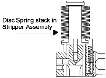 |
For more severe applications of a dynamic or highly corrosive nature, the Disc Springs will benefits from maintained lubrication, and are often housed in a oil or grease filled chamber.
............................................................................................................................................
|
| Disc Spring with Contract Flats and Reduced Thickness:
For Disc Springs with a thickness of more than 6mm, DIN 2093 specifies small contact surfaces at point I III in Addition to the rounded corners. These contact flats improve definition of the point of load application and reduce friction at the guide rod. Contact flat increase spring load which is to be compensated by a reduction in the thickness from 't' to 't'. |
............................................................................................................................................
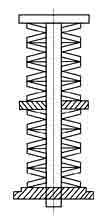
Stacking : |
Series Stacking: The cumulative effect of bearing point friction of large numbers of Disc Springs stacked in series, can result in the Disc Springs at each end of the stack deflecting more than those in the center. In extreme cases this may result in over-compression and premature failure of the end springs. A �rule of thumb� is that the length of the stacked Disc Springs should not exceed a length approximately equal to 3 times the outside diameter of the Disc Spring. |
| Stack Length : | |
When stacking Disc Springs, effort should be made to keep the stacks as short as possible. Friction and other influences make a stack more uneven. It deflects more on the side of the loading. This effect usually can be neglected for a "normal" spring stack, but not for long stacks. If it is longer, the stack can be stabilized by dividing it with guide washers, which as a rule of thumb should have a thickness of at least one and a half times the guide diameter. |
|
| |
|
|
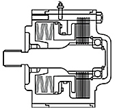
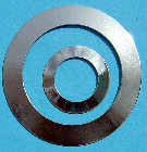
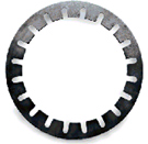
Ball Bearing Disc Springs & Washers (Plain, Slotted and Multi Wave)
There are some types of Ball bearing Disc Springs both plain and slotted & Preloading Bearing Washers. Ball-Bearing Disc Springs are used with radial Ball bearings to minimize vibration and shaft deflection. Proper preloading will increase bearing rigidity and eliminate excessive wear & tear and running noise.
Advantages of Ball Bearing Disc Springs Preloading Washers :
1. Significant increase or decrease in applied force even with small variation in deflection.
2. Backlash compensation & regressive curves help reduce preload variations changes
3. Very low force characteristics with very large deflection range
4. Multiplication of force by stacking of two or more in parallel.
5. Available in all size to accommodate all Ball bearing sizes.
6. Elimination of noise and play in Ball Bearings.
7. Round shape ensures equal distribution of load around the bearing ring.
Application of Preloaded Bearing Washers in Electric motors helps to reduce operating noise. The preload force remains practically constant even when there is axial displacement of the bearing as a result of thermal expansion. If preload is primarily to protect the bearing from vibration damage when stationary, then greater preload is required | |
Plain Ball Bearing Disc Springs
Ball Baring
Ref. No. | Diameter* De (mm) | Di (mm) | Thickness t (mm) | Unloaded height I0 (mm) | L0.50 (mm) | F 0.50 (N) | L0.75 (mm) | F0.75 (N) |
| 623 | | | 9.8 | 6.2 | 0.2 | 0.4 | 0.10 | 19 | 0.15 | 24 |
| 624 | | | 12.8 | 7.2 | 0.25 | 0.5 | 0.12 | 24 | 0.19 | 29 |
| | | 15.8 | 8.2 | 0.25 | 0.75 | 0.5 | 17 | 0.37 | 20 |
| 625 | 634 | | 15.8 | 8.2 | 0.25 | 0.55 | 0.15 | 20 | 0.22 | 23 |
| 626 | 635 | | 18.8 | 9.2 | 0.3 | 0.65 | 0.17 | 26 | 0.26 | 31 |
| 607 | | | 18.8 | 10.2 | 0.35 | 0.7 | 0.17 | 40 | 0.26 | 51 |
| 608 | 627 | | 21.8 | 12.3 | 0.35 | 0.75 | 0.20 | 38 | 0.30 | 46 |
| 609 | | | 23.7 | 14.3 | 0.4 | 0.9 | 0.25 | 69 | 0.37 | 80 |
| 6000 | 629 | | 25.7 | 14.3 | 0.4 | 0.9 | 0.25 | 54 | 0.37 | 64 |
| 6001 | | | 27.7 | 17.3 | 0.4 | 1.0 | 0.3 | 73 | 0.45 | 80 |
| 6200 | | | 29.7 | 17.3 | 0.4 | 1.1 | 0.35 | 80 | 0.52 | 82 |
| 6002 | 6201 | | 31.7 | 20.4 | 0.35 | 1.55 | 0.95 | 27 | 0.65 | 33 |
| 6300 | | | 34.6 | 20.4 | 0.4 | 1.1 | 0.35 | 60 | 0.52 | 61 |
| 6003 | 6202 | | 34.6 | 22.4 | 0.5 | 1.2 | 0.35 | 106 | 0.52 | 119 |
| 6301 | | | 36.6 | 20.4 | 0.5 | 1.3 | 0.40 | 103 | 0.6 | 111 |
| 6203 | | | 39.6 | 25.5 | 0.5 | 1.3 | 0.40 | 103 | 0.6 | 111 |
| 6004 | 6302 | | 41.6 | 25.5 | 0.5 | 1.4 | 0.45 | 113 | 0.67 | 114 |
| 6005 | 6204 | 6303 | 46.5 | 30.5 | 0.6 | 1.5 | 0.45 | 140 | 0.67 | 155 |
| 6205 | 6304 | | 51.5 | 35.5 | 0.6 | 1.5 | 0.45 | 124 | 0.67 | 135 |
| 6006 | | | 54.5 | 40.5 | 0.6 | 1.5 | 0.45 | 127 | 0.67 | 140 |
| 6007 | 6206 | 6305 | 61.5 | 40.5 | 0.7 | 1.8 | 0.55 | 164 | 0.82 | 186 |
| 6008 | | | 67.5 | 50.5 | 0.7 | 1.7 | 0.50 | 143 | 0.75 | 160 |
| 6306 | | | 71.5 | 45.5 | 0.7 | 2.1 | 0.7 | 190 | 1.05 | 185 |
| 6207 | | | 71.5 | 50.5 | 0.7 | 2.1 | 0.7 | 223 | 1.05 | 217 |
| 6048 | 6240 | 6334 | 74.5 | 55.5 | 0.6 | 2.9 | 1.75 | 88 | 1.17 | 91 |
| 6009 | | | 74.5 | 55.5 | 0.8 | 1.9 | 0.55 | 186 | 0.82 | 212 |
| 6307 | | | 79.5 | 50.5 | 0.8 | 2.3 | 0.75 | 228 | 1.12 | 228 |
| 6010 | 6208 | | 79.5 | 55.5 | 0.8 | 2.3 | 0.75 | 264 | 1.12 | 264 |
| 6209 | | | 84.5 | 60.5 | 0.9 | 2.5 | 0.8 | 352 | 1.2 | 357 |
| 6308 | | | 89.5 | 60.5 | 0.9 | 2.5 | 0.8 | 284 | 1.2 | 288 |
| 6011 | 6210 | | 89.5 | 65.5 | 0.9 | 2.5 | 0.8 | 330 | 1.2 | 333 |
| 6012 | | | 94.5 | 75.5 | 1 | 2.2 | 0.6 | 272 | 0.9 | 325 |
| 6309 | | | 99 | 65.5 | 1 | 2.6 | 0.8 | 274 | 1.2 | 293 |
| 6013 | 6211 | | 99 | 70.5 | 1 | 2.6 | 0.8 | 312 | 1.2 | 333 |
| 6310 | | | 109 | 70.5 | 1.25 | 2.7 | 0.73 | 294 | 1.09 | 356 |
| 6014 | 6212 | | 109 | 75.5 | 1.25 | 2.7 | 0.73 | 327 | 1.09 | 394 |
| 6015 | | | 114 | 90.5 | 1.25 | 2.45 | 0.6 | 311 | 0.9 | 396 |
| 6311 | | | 119 | 75.5 | 1.25 | 2.8 | 0.78 | 270 | 1.16 | 319 |
| 6213 | | | 119 | 85.5 | 1.25 | 2.8 | 0.78 | 331 | 1.16 | 391 |
| 6016 | 6214 | | 124 | 90.5 | 1.25 | 3 | 0.88 | 392 | 1.31 | 441 |
| 6312 | | | 129 | 85.5 | 1.25 | 3.2 | 0.98 | 375 | 1.46 | 402 |
| 6017 | 6215 | | 129 | 95.5 | 1.25 | 3.2 | 0.98 | 328 | 1.46 | 441 |
| 6313 | | | 139 | 90.5 | 1.25 | 3.25 | 1 | 329 | 1.5 | 353 |
| 6018 | 6216 | | 139 | 101 | 1.25 | 3.25 | 1 | 398 | 1.5 | 427 |
| 6314 | | | 149 | 95.5 | 1.5 | 3.2 | 0.85 | 312 | 1.28 | 380 |
| 6020 | 6217 | | 149 | 106 | 1.5 | 3.2 | 0.85 | 368 | 1.28 | 448 |
| 6315 | | | 159 | 101 | 1.5 | 3.5 | 1 | 356 | 1.5 | 409 |
| 6021 | 6218 | | 159 | 111 | 1.5 | 3.5 | 1 | 415 | 1.5 | 477 |
| 6316 | | | 169 | 111 | 1.5 | 3.8 | 1.1 | 432 | 1.73 | 472 |
| 6022 | 6219 | | 169 | 121 | 1.5 | 3.8 | 1.15 | 497 | 1.73 | 542 |
| 6317 | | | 179 | 121 | 2 | 4.2 | 1.1 | 702 | 1.65 | 861 |
| 6024 | 6220 | | 179 | 126 | 2 | 4.2 | 1.1 | 761 | 1.65 | 934 |
| 6318 | | | 189 | 121 | 2 | 4.3 | 1.15 | 628 | 1.73 | 760 |
| 6221 | | | 189 | 131 | 2 | 4.3 | 1.15 | 702 | 1.73 | 849 |
| 6319 | | | 198 | 131 | 2 | 4.5 | 1.25 | 691 | 1.88 | 813 |
| 6026 | 6222 | | 198 | 141 | 2 | 4.5 | 1.25 | 779 | 1.88 | 917 |
| 6224 | 6320 | | 213 | 151 | 2.25 | 4.5 | 1.12 | 746 | 1.69 | 941 |
| 6030 | 6321 | | 223 | 161 | 2.25 | 4.6 | 1.17 | 747 | 1.76 | 933 |
| 6226 | | | 228 | 161 | 2.25 | 4.95 | 1.35 | 864 | 2.02 | 1030 |
| 6322 | | | 238 | 161 | 2.25 | 5.25 | 1.5 | 886 | 2.25 | 1020 |
| 6228 | | | 248 | 171 | 2.5 | 5 | 1.25 | 795 | 1.88 | 1000 |
| 6324 | | | 258 | 171 | 2.5 | 5.5 | 1.5 | 928 | 2.25 | 1108 |
| 6230 | | | 268 | 181 | 2.5 | 5.7 | 1.6 | 990 | 2.4 | 1160 |
| 6326 | | | 268 | 181 | 2.5 | 6 | 1.75 | 1020 | 2.63 | 1160 |
| 6232 | | | 288 | 191 | 2.75 | 5.75 | 1.5 | 931 | 2.25 | 1150 |
| 6328 | | | 298 | 191 | 2.75 | 6.35 | 1.8 | 1130 | 2.7 | 1310 |
| 6234 | | | 308 | 202 | 3 | 6.1 | 1.55 | 1050 | 2.33 | 1300 |
| 6236 | 6330 | | 318 | 212 | 3 | 6.2 | 1.6 | 1060 | 2.4 | 1300 |
| 6238 | 6332 | | 338 | 232 | 3 | 6.6 | 1.8 | 1180 | 2.7 | 1410 |
| 6240 | 6334 | | 358 | 242 | 3 | 7.2 | 2.1 | 1350 | 3.15 | 1530 |
|
Slotted Ball Bearing Disc Springs
Ball Baring
designation No. | Diameter* De (mm) | Di (mm) | Thickness t (mm) | Unloaded height I0 (mm) | L0.50 (mm) | F 0.50 (N) | L0.75 (mm) | F0.75 (N) |
| 623 | | | 9.8 | 6.2 | 0.15 | 0.6 | 0.23 | 9 | 0.35 | 13 |
| 624 | | | 12.8 | 7.2 | 0.2 | 0.65 | 0.23 | 16 | 0.35 | 18 |
| 625 | 634 | | 15.8 | 8.2 | 0.25 | 0.75 | 0.25 | 17 | 0.4 | 20 |
| 626 | 635 | | 18.8 | 9.2 | 0.25 | 1 | 0.38 | 17 | 0.55 | 20 |
| 607 | | | 18.8 | 10.2 | 0.25 | 1.05 | 0.4 | 19 | 0.6 | 24 |
| 608 | 627 | | 21.8 | 12.3 | 0.25 | 1.25 | 0.5 | 19 | 0.75 | 24 |
| 609 | | | 23.7 | 14.3 | 0.3 | 1.3 | 0.5 | 21 | 0.75 | 25 |
| 6000 | 629 | | 25.7 | 14.3 | 0.3 | 1.4 | 0.55 | 24 | 0.8 | 28 |
| 6001 | | | 27.7 | 17.3 | 0.35 | 1.45 | 0.55 | 25 | 0.8 | 31 |
| 6200 | | | 29.7 | 17.3 | 0.35 | 1.55 | 0.6 | 26 | 0.9 | 32 |
| 6002 | 6201 | | 31.7 | 20.4 | 0.35 | 1.55 | 0.6 | 27 | 0.9 | 33 |
| 6300 | | | 34.6 | 20.4 | 0.35 | 1.65 | 0.65 | 27 | 1 | 32 |
| 6003 | 6202 | | 34.6 | 22.4 | 0.35 | 1.55 | 0.6 | 27 | 0.9 | 32 |
| 6301 | | | 36.6 | 20.4 | 0.4 | 1.9 | 0.75 | 31 | 1.1 | 35 |
| 6203 | | | 39.6 | 25.5 | 0.4 | 1.9 | 0.75 | 33 | 1.1 | 37 |
| 6004 | 6302 | | 41.6 | 25.5 | 0.45 | 2.05 | 0.80 | 34 | 1.2 | 39 |
| 6005 | 6204 | 6303 | 46.5 | 30.5 | 0.45 | 2.05 | 0.80 | 39 | 1.2 | 44 |
| 6205 | 6304 | | 51.5 | 35.5 | 0.45 | 2.1 | 0.85 | 42 | 1.25 | 47 |
| 6006 | | | 54.5 | 40.5 | 0.45 | 2.15 | 0.85 | 42 | 1.3 | 53 |
| 6007 | 6206 | 6305 | 61.5 | 40.5 | 0.55 | 2.55 | 1.00 | 49 | 1.5 | 54 |
| 6008 | | | 67.5 | 50.5 | 0.5 | 2.6 | 1.05 | 76 | 1.6 | 78 |
| 6306 | | | 71.5 | 45.5 | 0.6 | 2.9 | 1.15 | 71 | 1.7 | 74 |
| 6207 | | | 71.5 | 50.5 | 0.6 | 2.9 | 1.15 | 127 | 1.7 | 127 |
| 6009 | | | 74.5 | 55.5 | 0.6 | 2.9 | 1.15 | 88 | 1.7 | 91 |
| 6307 | | | 79.5 | 50.5 | 0.7 | 3.1 | 1.2 | 78 | 1.8 | 78 |
| 6308 | | | 89.5 | 60.5 | 0.8 | 3.3 | 1.25 | 90 | 1.9 | 104 |
| 6011 | 6210 | | 89.5 | 65.5 | 0.8 | 3.4 | 1.3 | 180 | 1.95 | 189 |
| 6012 | | | 94.5 | 75.5 | 0.8 | 3.45 | 1.35 | 191 | 2 | 206 |
|
|
|
|
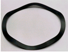
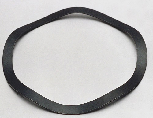
WAVE SPRING WASHERS
There are some types of wave Spring washers as per DIN 137 & DIN 6904 those made from prime quality spring steel, stainless steel, copper and other material which are readily available in very standard sizes. Wave washers are wavy metal washers designed to offer a compensating spring force and maintain a load or take up shock. These are the disc of irregular shape formed in such a way that when loaded it deflects, acts like a spring, and provides a preload between two surfaces. Wave washers are very useful for limited radial space and moderate thrust load e.g. Axial loading of Ball bearing. | |
| The number of waves can be two, three or ~ more. The spring rate is proportional to the number of waves raised to the fourth power.
Wave Washers are generally preferred as cushion spacers between parts on shafts or to take up the probable deviation in assembled parts. These are positioned underneath a nut, an axle bearing or a joint to reduce friction, avoid leakage, isolate, stop loosening or distribute pressure. IIS has ready stock of all the sizes. For details checkout our website. |
|
TABLE 1 : DIMENSIONS OF TYPE B SPRING WASHERS |
| | | S | H |
| Nominal size | d1 1) H14 | d2 1) js16 | Nominal size | Limit deviations | min. | max. |
| 32) | 3.2 | 8 | 0.5 | +0.05 | 0.8 | 1.6 |
| 3.52) | 3.7 | 8 | 0.5 | +0.05 | 0.9 | 1.8 |
| 4 | 4.3 | 9 | 0.5 | +0.05 | 1 | 2 |
| 5 | 5.3 | 11 | 0.5 | +0.05 | 1.1 | 2.2 |
|
|
|
|
|
|
|
| 6 | 6.4 | 12 | 0.5 | +0.05 | 1.3 | 2.6 |
| 7 | 7.4 | 14 | 0.8 | +0.06 | 1.5 | 3 |
| 8 | 8.4 | 15 | 0.8 | +0.06 | 1.5 | 3 |
|
|
|
|
|
|
|
| 10 | 10.5 | 21 | 1 | +0.07 | 2.1 | 4.2 |
| 12 | 13 | 24 | 1.2 | +0.07 | 2.5 | 5 |
| 14 | 15 | 28 | 1.6 | +0.08 | 3 | 6 |
|
|
|
|
|
|
|
| 16 | 17 | 30 | 1.6 | +0.08 | 3.2 | 6.4 |
| 18 | 19 | 34 | 1.6 | +0.08 | 3.3 | 6.6 |
| 20 | 21 | 36 | 1.6 | +0.08 | 3.7 | 7.4 |
|
|
|
|
|
|
|
| 22 | 23 | 40 | 1.8 | +0.01 | 3.9 | 7.8 |
| 24 | 25 | 44 | 1.8 | +0.01 | 4.1 | 8.2 |
| 27 | 28 | 50 | 2 | +0.01 | 4.7 | 9.4 |
|
|
|
|
|
|
|
| 30 | 31 | 56 | 2.2 | +0.01 | 5 | 10 |
| 33 | 34 | 60 | 2.2 | +0.01 | 5.3 | 10.6 |
| 36 | 37 | 68 | 2.5 | +0.015 | 5.8 | 11.6 |
1) The diameter tolerances specified apply to spring washers when pressed flat. The tolerance on coaxiality between d, and d, (related to d2) shall be 1/2 IT 14
2) Values to be complied with in the spring force test as described in DIN 267 Part 26 have not as yet been specified for this size. |
|
|
|
| source: http://www.internationalsprings.com |
|
|
|
| | | | |
|
|
| | | | |
|


Tidak ada komentar:
Posting Komentar