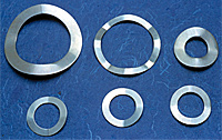
Rumah maya tuk menyimpan hal-hal yang ringan dan terbuka buat siapa saja. Disini anda bisa mencari dan berbagi apa saja , ilmu, hiburan, musik, ebook dll. (Konten ini diambil dari berbagai sumber internet public domain. Jika ada keberatan, konten yang melanggar hak cipta, beritahu kami. Kami tidak akan ragu menghapusnya.
DALAM BAHASA SUNDA
Tampilkan postingan dengan label Pegas. Tampilkan semua postingan
Jumat, 05 Oktober 2012
Senin, 19 September 2011
HOW PRODUCT ARE MADE - SPRINGS
A spring is a device that changes its shape in response to an external force, returning to its original shape when the force is removed. The energy expended in deforming the spring is stored in it and can be recovered when the spring returns to its original shape. Generally, the amount of the shape change is directly related to the amount of force exerted. If too large a force is applied, however, the spring will permanently deform and never return to its original shape.
Still another variation of coiled springs is the watch spring, which is coiled into a flat spiral rather than a cylinder or cone. One end of the spring is at the center of the spiral, and the other is at its outer edge.
Some springs are fashioned without coils. The most common example is the leaf spring, which is shaped like a shallow arch; it is commonly used for automobile suspension systems. Another type is a disc spring, a washer-like device that is shaped like a truncated cone. Open-core cylinders of solid, elastic material can also act as springs. Non-coil springs generally function as compression springs.
The next significant development in the history of springs came in the Middle Ages. A power saw devised by Villard de Honnecourt about 1250 used a water wheel to push the saw blade in one direction, simultaneously bending a pole; as the pole returned to its unbent state, it pulled the saw blade in the opposite direction.
Coiled springs were developed in the early fifteenth century. By replacing the system of weights that commonly powered clocks with a wound spring mechanism, clockmakers

were able to fashion reliable, portable timekeeping devices. This advance made precise celestial navigation possible for ocean-going ships.
In the eighteenth century, the Industrial Revolution spurred the development of mass-production techniques for making springs. During the 1780s, British locksmith Joseph Bramah used a spring winding machine in his factory. Apparently an adaptation of a lathe, the machine carried a reel of wire in place of a cutting head. Wire from the reel was wrapped around a rod secured in the lathe. The speed of the lead screw, which carried the reel parallel to the spinning rod, could be adjusted to vary the spacing of the spring's coils.
Common examples of current spring usage range from tiny coils that support keys on cellular phone touchpads to enormous coils that support entire buildings and protect them from earthquake vibration.
Other metals that are sometimes used to make springs are beryllium copper alloy, phosphor bronze, and titanium. Rubber or urethane may be used for cylindrical, non-coil springs. Ceramic material has been developed for coiled springs in very high-temperature environments. One-directional glass fiber composite materials are being tested for possible use in springs.
Approximately one-third of defective springs result from production problems. The other two-thirds are caused by deficiencies in the wire used to form the springs. In 1998, researchers reported the development of a wire coilability test (called FRACMAT) that could screen out inadequate wire prior to manufacturing springs.
Computer-operated coiling machines improve quality in two ways. First, they control the diameter and pitch of the spring more precisely than manual operations can. Second, through the use of piezoelectric materials, whose size varies with electrical input, CNC coiling heads can precisely adjust in real time to measurements of spring characteristics. As a result, these intelligent machines produce fewer springs that must be rejected for not meeting specifications.
Medical devices also use very small springs. A coiled spring has been developed for use in the insertion end of a catheter or an endoscope. Made of wire 0.0012 in (30 micrometers or 0.030 mm) in diameter, the spring is 0.0036 in (0.092 mm) thick—about the same as a human hair. The Japanese company that developed this spring is attempting to make it even smaller.
The ultimate miniaturization accomplished so far was accomplished in 1997 by an Austrian chemist named Bernard Krautler. He built a molecular spring by stringing 12 carbon atoms together and attaching a vitamin B12 molecule to each end of the chain by means of a cobalt atom. In the relaxed state the chain has a zigzag shape; when it is wetted with water, however, it kinks tightly together. Adding cyclodextrin causes the chain to return to its relaxed state. No practical application of this spring has yet been found, but research continues.
"H & R Spring Overview." http://www.hrsprings.com/abouthr.html (November 2000).
Silberstein, Dave. "How to Make Springs." http://home.earthlink.net/-bazillion/intro.html (November 2000).
Background
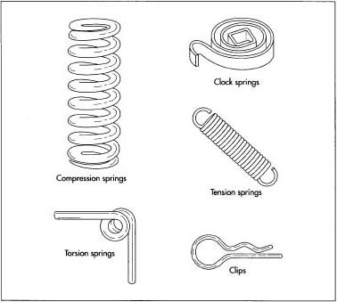
There are several types of springs. One of the most common consists of wire wound into a cylindrical or conical shape. An extension spring is a coiled spring whose coils normally touch each other; as a force is applied to stretch the spring, the coils separate. In contrast, a compression spring is a coiled spring with space between successive coils; when a force is applied to shorten the spring, the coils are pushed closer together. A third type of coiled spring, called a torsion spring, is designed so the applied force twists the coil into a tighter spiral. Common examples of torsion springs are found in clipboards and butterfly hair clips.Still another variation of coiled springs is the watch spring, which is coiled into a flat spiral rather than a cylinder or cone. One end of the spring is at the center of the spiral, and the other is at its outer edge.
Some springs are fashioned without coils. The most common example is the leaf spring, which is shaped like a shallow arch; it is commonly used for automobile suspension systems. Another type is a disc spring, a washer-like device that is shaped like a truncated cone. Open-core cylinders of solid, elastic material can also act as springs. Non-coil springs generally function as compression springs.
History
Very simple, non-coil springs have been used throughout history. Even a resilient tree branch can be used as a spring. More sophisticated spring devices date to the Bronze Age, when eyebrow tweezers were common in several cultures. During the third century B.C., Greek engineer Ctesibius of Alexandria developed a process for making "springy bronze" by increasing the proportion of tin in the copper alloy, casting the part, and hardening it with hammer blows. He attempted to use a combination of leaf springs to operate a military catapult, but they were not powerful enough. During the second century B.C., Philo of Byzantium, another catapult engineer, built a similar device, apparently with some success. Padlocks were widely used in the ancient Roman empire, and at least one type used bowed metal leaves to keep the devices closed until the leaves were compressed with keys.The next significant development in the history of springs came in the Middle Ages. A power saw devised by Villard de Honnecourt about 1250 used a water wheel to push the saw blade in one direction, simultaneously bending a pole; as the pole returned to its unbent state, it pulled the saw blade in the opposite direction.
Coiled springs were developed in the early fifteenth century. By replacing the system of weights that commonly powered clocks with a wound spring mechanism, clockmakers

A diagram depicting spring coiling done by a CNC machine.
In the eighteenth century, the Industrial Revolution spurred the development of mass-production techniques for making springs. During the 1780s, British locksmith Joseph Bramah used a spring winding machine in his factory. Apparently an adaptation of a lathe, the machine carried a reel of wire in place of a cutting head. Wire from the reel was wrapped around a rod secured in the lathe. The speed of the lead screw, which carried the reel parallel to the spinning rod, could be adjusted to vary the spacing of the spring's coils.
Common examples of current spring usage range from tiny coils that support keys on cellular phone touchpads to enormous coils that support entire buildings and protect them from earthquake vibration.
Raw Materials
Steel alloys are the most commonly used spring materials. The most popular alloys include high-carbon (such as the music wire used for guitar strings), oil-tempered low-carbon, chrome silicon, chrome vanadium, and stainless steel.Other metals that are sometimes used to make springs are beryllium copper alloy, phosphor bronze, and titanium. Rubber or urethane may be used for cylindrical, non-coil springs. Ceramic material has been developed for coiled springs in very high-temperature environments. One-directional glass fiber composite materials are being tested for possible use in springs.
Design
Various mathematical equations have been developed to describe the properties of springs, based on such factors as wire composition and size, spring coil diameter, the number of coils, and the amount of expected external force. These equations have been incorporated into computer software to simplify the design process.The Manufacturing Process
The following description focuses on the manufacture of steel-alloy, coiled springs.Coiling
- 1 Cold winding. Wire up to 0.75 in (18 mm) in diameter can be coiled at room temperature using one of two basic techniques. One consists of winding the wire around a shaft called an arbor or mandrel. This may be done on a dedicated spring-winding machine, a lathe, an electric hand drill with the mandrel secured in the chuck, or a winding machine operated by hand cranking. A guiding mechanism, such as the lead screw on a lathe, must be used to align the wire into the desired pitch (distance between successive coils) as it wraps around the mandrel.
Alternatively, the wire may be coiled without a mandrel. This is generally done with a central navigation computer (CNC) machine.
The wire is pushed forward over a support block toward a grooved head that deflects the wire, forcing it to bend. The head and support block can be moved relative to each other in as many as five directions to control the diameter and pitch of the spring that is being formed.
Examples of different types of springs.
For extension or torsion springs, the ends are bent into the desired loops, hooks, or straight sections after the coiling operation is completed. - 2 Hot winding. Thicker wire or bar stock can be coiled into springs if the metal is heated to make it flexible. Standard industrial coiling machines can handle steel bar up to 3 in (75 mm) in diameter, and custom springs have reportedly been made from bars as much as 6 in (150 mm) thick. The steel is coiled around a mandrel while red hot. Then it is immediately removed from the coiling machine and plunged into oil to cool it quickly and harden it. At this stage, the steel is too brittle to function as a spring, and it must subsequently be tempered.
Hardening
- 3 Heat treating. Whether the steel has been coiled hot or cold, the process has created stress within the material. To relieve this stress and allow the steel to maintain its characteristic resilience, the spring must be tempered by heat treating it. The spring is heated in an oven, held at the appropriate temperature for a predetermined time, and then allowed to cool slowly. For example, a spring made of music wire is heated to 500°F (260°C) for one hour.
Finishing
- 4 Grinding. If the design calls for flat ends on the spring, the ends are ground at this stage of the manufacturing process. The spring is mounted in a jig to ensure the correct orientation during grinding, and it is held against a rotating abrasive wheel until the desired degree of flatness is obtained. When highly automated equipment is used, the spring is held in a sleeve while both ends are ground simultaneously, first by coarse wheels and then by finer wheels. An appropriate fluid (water or an oil-based substance) may be used to cool the spring, lubricate the grinding wheel, and carry away particles during the grinding.
- 5 Shot peening. This process strengthens the steel to resist metal fatigue and cracking during its lifetime of repeated flexings. The entire surface of the spring is exposed to a barrage of tiny steel balls that hammer it smooth and compress the steel that lies just below the surface.
- 6 Setting. To permanently fix the desired length and pitch of the spring, it is fully compressed so that all the coils touch each other. Some manufacturers repeat this process several times.
- 7 Coating. To prevent corrosion, the entire surface of the spring is protected by painting it, dipping it in liquid rubber, or plating it with another metal such as zinc or chromium. One process, called mechanical plating, involves tumbling the spring in a container with metallic powder, water, accelerant chemicals, and tiny glass beads that pound the metallic powder onto the spring surface.
Alternatively, in electroplating, the spring is immersed in an electrically conductive liquid that will corrode the plating metal but not the spring. A negative electrical charge is applied to the spring. Also immersed in the liquid is a supply of the plating metal, and it is given a positive electrical charge. As the plating metal dissolves in the liquid, it releases positively charged molecules that are attracted to the negatively charged spring, where they bond chemically. Electroplating makes carbon steel springs brittle, so shortly after plating (less than four hours) they must be baked at 325-375°F (160-190°C) for four hours to counteract the embrittlement. - 8 Packaging. Desired quantities of springs may simply be bulk packaged in boxes or plastic bags. However, other forms of packaging have been developed to minimize damage or tangling of springs. For example, they may be individually bagged, strung onto wires or rods, enclosed in tubes, or affixed to sticky paper.
Quality Control
Various testing devices are used to check completed springs for compliance with specifications. The testing devices measure such properties as the hardness of the metal and the amount of the spring's deformation under a known force. Springs that do not meet the specifications are discarded. Statistical analysis of the test results can help manufacturers identify production problems and improve processes so fewer defective springs are produced.Approximately one-third of defective springs result from production problems. The other two-thirds are caused by deficiencies in the wire used to form the springs. In 1998, researchers reported the development of a wire coilability test (called FRACMAT) that could screen out inadequate wire prior to manufacturing springs.
Computer-operated coiling machines improve quality in two ways. First, they control the diameter and pitch of the spring more precisely than manual operations can. Second, through the use of piezoelectric materials, whose size varies with electrical input, CNC coiling heads can precisely adjust in real time to measurements of spring characteristics. As a result, these intelligent machines produce fewer springs that must be rejected for not meeting specifications.
The Future
Demands of the rapidly growing computer and cellular phone industries are pushing spring manufacturers to develop reliable, cost-effective techniques for making very small springs. Springs that support keys on touchpads and keyboards are important, but there are less apparent applications as well. For instance, a manufacturer of test equipment used in semiconductor production has developed a microspring contact technology. Thousands of tiny springs, only 40 mils (0.040 in or 1 mm) high, are bonded to individual contact points of a semiconductor wafer. When this wafer is pressed against a test instrument, the springs compress, establishing highly reliable electrical connections.Medical devices also use very small springs. A coiled spring has been developed for use in the insertion end of a catheter or an endoscope. Made of wire 0.0012 in (30 micrometers or 0.030 mm) in diameter, the spring is 0.0036 in (0.092 mm) thick—about the same as a human hair. The Japanese company that developed this spring is attempting to make it even smaller.
The ultimate miniaturization accomplished so far was accomplished in 1997 by an Austrian chemist named Bernard Krautler. He built a molecular spring by stringing 12 carbon atoms together and attaching a vitamin B12 molecule to each end of the chain by means of a cobalt atom. In the relaxed state the chain has a zigzag shape; when it is wetted with water, however, it kinks tightly together. Adding cyclodextrin causes the chain to return to its relaxed state. No practical application of this spring has yet been found, but research continues.
Where to Learn More
Other
"Coil Spring Making Process—Automotive." Industrial Engineers and Spring Makers. http://www.ozemail.com (November 2000)."H & R Spring Overview." http://www.hrsprings.com/abouthr.html (November 2000).
Silberstein, Dave. "How to Make Springs." http://home.earthlink.net/-bazillion/intro.html (November 2000).
— Loretta Hall
Read more: How springs is made - material, manufacture, making, history, how to make, used, composition, machine, History, Raw Materials, Design, The Manufacturing Process of springs http://www.madehow.com/Volume-6/Springs.html#ixzz1YO1yh8Ss
Sumber:http://www.madehow.com/Volume-6/Springs.html
Rabu, 27 Juli 2011
Spring Creator Calculator (Easy, Efficient, Effective) from Planetspring.com
Planetspring.com has created 3 spring calculators that were designed for simplicity and efficiency. These three calculators can design extension springs, helical springs, and torsion springs. We have made spring calculation quick and easy. Click on one of our 3 calculators (the torsion spring calculator, extension spring calculator or the compression spring calculator) and begin your spring design.
The first of our calculators is the compression springs calculator. If you are designing a compression spring, coil spring, or helical spring this calculator is the one you will need. Most spring compression calculators are tricky and do not provide you with all of the design considerations you will need. Our coil compression springs calculator only requires 4 inputs to compute your compression spring design. The calculator gives you 19 outputs, which will be everything an engineer needs to manufacture your coil springs, including the spring rate and the spring constant. The only thing you need to know before using our spring calculator is how to measure a compression spring. You will need to know how to measure the outer diameter of the coil springs, the free length, and the wire diameter of your coil springs. You will also need to know how many active coils are in your spring. If you have any questions on how to measure a compression spring please watch our “How To Measure a Compression Spring” video at the top of the compression spring calculator page. If you would like to do a compression spring calculation using compression spring formulas please visit our compression springs technical article.
Our second calculator is the extension spring calculator. If you are designing a tension spring our calculator is the easiest and most effective way to do it. To begin your extension spring design you will need to know how to measure an extension spring. Please watch our “How To Measure an Extension Spring” video at the top of the extension spring calculator page. Designing your tension springs requires that you know only 3 inputs and what type of hooks are on your extension springs. After those values have been inputted the calculator will give you 18 outputs, which will be everything an engineer will need to manufacture your spring. Calculating spring constant or a spring rate calculation by simply using the extension spring formulas can be very difficult. However, if you would like to use the extension spring formulas please visit our extension springs technical article.
The last of our calculators is the torsion spring calculator. Other torsion spring calculators on the web are confusing and hard to work with. Our torsion spring calculator is simple and efficient for calculating your torsion springs design. In order to use our calculator you will need to know how to measure torsion springs. If you do not know how to measure a torsion spring or you need an example of a torsion spring please watch our “How to Measure a Torsion Spring” video at the top of the torsion spring calculator page. In order to calculate your torsion springs you will only need 3 inputs. You will also need to know what type of wire you want your torsion spring made out of, for example you may need a stainless steel torsion spring. The calculator will then give you 13 outputs, which will be everything an engineer needs to manufacture your torsion springs. When calculating spiral torsion springs by hand or doing any type of spring constant physics you will need the torsion springs formula. These can be found in our torsion springs technical article along with a great explanation of torsion springs.
Please click on the calculator you would like to begin using and input your values. Again if you have any questions on how to measure your spring, please watch the videos at the top of this page. If you are unsure how to work a particular calculator, please watch that calculator’s how to video at the top of each page.
Planetspring.com @youtube
Source:http://www.planetspring.com/pages/live-online-spring-calculators.php
Selasa, 19 Juli 2011
Belleville Washer/ Spring
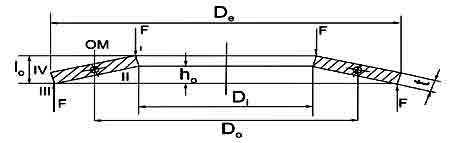
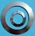
A Belleville washer, also known as a coned-disc spring, conical spring washer, disc spring, Belleville spring or cupped spring washer, is a type of spring shaped like a washer. It has a frusto-conical shape which gives the washer a spring characteristic. The Belleville name comes from the inventor Julian F. Belleville.
Belleville springs are a type of disc-shaped washer with an extremely high tensile strength. Originally developed in the mid-19th century by Julian Belleville, belleville springs are used in a variety of environments in which a heavy load bearing ability is required. Many high performance cars use a type of belleville spring in their shock absorbing systems, and belleville springs are also used in manufacturing equipment, as well as electronics.
Belleville springs can be made in a wide range of sizes, from very small washers to very large discs. In shape, they resemble a shallow soup bowl with the bottom cut out, and they are generally made from tempered steel and other similar metals that can stand up to immense pressures. Most manufacturers pre-stress belleville springs before delivering them to consumers, to make sure that they won't fail in practical applications.
Because of their construction, belleville springs can be subject to very heavy loads, and they will distribute the weight evenly around their circumference. As a result, they can be used to hold substantial loads and to distance parts of machinery from each other. They are highly useful in areas subject to thermal expansion or contraction, vibration, high bolt loads, and bolt creep, in which bolts may move around or wedge themselves out.
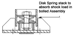
In the simplest of applications, belleville springs may be placed convex side out between a bolt and the surface they are attaching to. Sometimes, a small washer is used to help further balance the load, although the belleville spring is usually strong enough on its own. If a washer is used, it is placed under the outside diameter of the spring. When the bolt is subjected to stress, the belleville spring will help to distribute it evenly so that the bolt won't move or inadvertently release.
There are a number of other configurations for belleville springs in practical use, however. Sometimes they are installed in a parallel stack, increasing the amount of load they can accept. In other cases, the springs may be stacked in a series, either in front-to-front or back-to-back springs, to increase deflection. In a parallel series, the two systems are combined to increase load bearing ability and deflection. In all instances, belleville springs are said to have reached their maximum load capacity when they have flattened out.
Belleville springs are in use in a wide variety of commercial and consumer environments. In many instances in which the ability to withstand a heavy load in a small space is required, belleville springs are a good choice to balance that load safely and evenly.
Some properties of Belleville washers include: high fatigue life, better space utilization, low creep tendency, and high load capacity with a small spring deflection.
Belleville springs are also used in a number of landmines e.g. the American M19, M15, M14, M1 and the Swedish Tret-Mi.59. The target (a person or vehicle) exerts pressure on the belleville spring, causing it to exceed a trigger threshold and flip the adjacent firing pin downwards into a stab detonator, firing both it and the surrounding booster charge and main explosive filling.
They may also be used as locking devices, but only in applications with low dynamic loads, such as down-tube shifters for bicycles. Belleville washers are seen on Formula One cars, as they provide extremely detailed tuning ability. The World War II-vintage German Junkers Ju 88 aircraft's single strut main gear made primary use of belleville washers as its main shock absorption mechanism. At least one modern aircraft design, the Cirrus SR2x series, uses a Belleville washer setup to damp out nose gear oscillations (or "shimmy").
Belleville washers have been used as return springs in artillery pieces, one example being the French Canet range of marine/coastal cannon from the late 1800's (75 mm, 120mm, 152 mm).
Another example where they aid locking is a joint that experiences a large amount of thermal expansion and contraction. They will supply the required pre-load, but the bolt may have an additional locking mechanism (like Loctite) that would fail without the Belleville.
Example: 1 Spring is considered to be 1 in Parallel, 1 in Series. (This notation is needed for load calculations)
If n = # of springs in a stack, then: Parallel Stack (n in parallel, 1 in series) - Deflection is equal to that of one spring, Load is equal to that of n x 1 spring. i.e. Stack of 4 in parallel, 1 in series will have the same deflection as that of one spring and the load will be 4 times higher than that of one spring.
Series Stack (1 in parallel, n in series) - Deflection is equal to n x 1 spring, load is equal to that of one spring. i.e. Stack of 1 in parallel, 4 in series will have the same load of one spring and the deflection will be 4 times greater.
In a series stack, the deflection is not exactly proportional to the number of springs. This is because of a bottoming out effect when the springs are compressed to flat. The contact surface area increases once the spring is deflected beyond 95%. This decreases the moment arm and the spring will offer a greater spring resistance. Hysteresis can be used to calculate predicted deflections in a series stack. The number of springs used in a series stack is not as much of an issue as in parallel stacks.
Belleville washers are useful for adjustments because different thicknesses can be swapped in and out and they can be configured differently to achieve essentially infinite tunability of spring rate while only filling up a small part of the technician's tool box. They are ideal in situations where a heavy spring force is required with minimal free length and compression before reaching solid height. The downside, though, is weight, and they are severely travel limited compared to a conventional coil spring when free length is not an issue.
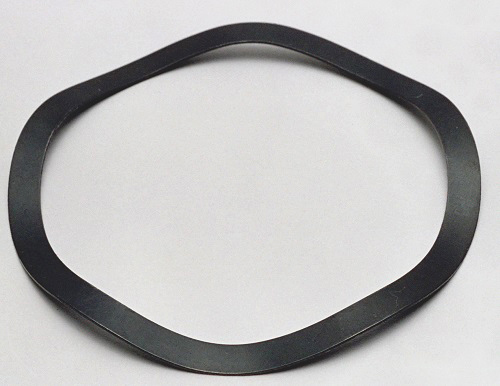
A similar device is a wave washer.
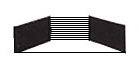
The total spring coefficient is:
Belleville springs are a type of disc-shaped washer with an extremely high tensile strength. Originally developed in the mid-19th century by Julian Belleville, belleville springs are used in a variety of environments in which a heavy load bearing ability is required. Many high performance cars use a type of belleville spring in their shock absorbing systems, and belleville springs are also used in manufacturing equipment, as well as electronics.
Belleville springs can be made in a wide range of sizes, from very small washers to very large discs. In shape, they resemble a shallow soup bowl with the bottom cut out, and they are generally made from tempered steel and other similar metals that can stand up to immense pressures. Most manufacturers pre-stress belleville springs before delivering them to consumers, to make sure that they won't fail in practical applications.
Because of their construction, belleville springs can be subject to very heavy loads, and they will distribute the weight evenly around their circumference. As a result, they can be used to hold substantial loads and to distance parts of machinery from each other. They are highly useful in areas subject to thermal expansion or contraction, vibration, high bolt loads, and bolt creep, in which bolts may move around or wedge themselves out.
In the simplest of applications, belleville springs may be placed convex side out between a bolt and the surface they are attaching to. Sometimes, a small washer is used to help further balance the load, although the belleville spring is usually strong enough on its own. If a washer is used, it is placed under the outside diameter of the spring. When the bolt is subjected to stress, the belleville spring will help to distribute it evenly so that the bolt won't move or inadvertently release.
There are a number of other configurations for belleville springs in practical use, however. Sometimes they are installed in a parallel stack, increasing the amount of load they can accept. In other cases, the springs may be stacked in a series, either in front-to-front or back-to-back springs, to increase deflection. In a parallel series, the two systems are combined to increase load bearing ability and deflection. In all instances, belleville springs are said to have reached their maximum load capacity when they have flattened out.
Belleville springs are in use in a wide variety of commercial and consumer environments. In many instances in which the ability to withstand a heavy load in a small space is required, belleville springs are a good choice to balance that load safely and evenly.
Design and use
Belleville washers are typically used as springs, or to apply a pre-load or flexible quality to a bolted joint or bearing.Some properties of Belleville washers include: high fatigue life, better space utilization, low creep tendency, and high load capacity with a small spring deflection.
Belleville springs are also used in a number of landmines e.g. the American M19, M15, M14, M1 and the Swedish Tret-Mi.59. The target (a person or vehicle) exerts pressure on the belleville spring, causing it to exceed a trigger threshold and flip the adjacent firing pin downwards into a stab detonator, firing both it and the surrounding booster charge and main explosive filling.
They may also be used as locking devices, but only in applications with low dynamic loads, such as down-tube shifters for bicycles. Belleville washers are seen on Formula One cars, as they provide extremely detailed tuning ability. The World War II-vintage German Junkers Ju 88 aircraft's single strut main gear made primary use of belleville washers as its main shock absorption mechanism. At least one modern aircraft design, the Cirrus SR2x series, uses a Belleville washer setup to damp out nose gear oscillations (or "shimmy").
Belleville washers have been used as return springs in artillery pieces, one example being the French Canet range of marine/coastal cannon from the late 1800's (75 mm, 120mm, 152 mm).
Another example where they aid locking is a joint that experiences a large amount of thermal expansion and contraction. They will supply the required pre-load, but the bolt may have an additional locking mechanism (like Loctite) that would fail without the Belleville.
Stacking
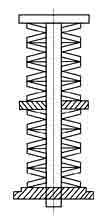
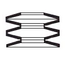
Multiple Belleville washers may be stacked to modify the spring constant or amount of deflection. Stacking in the same direction will add the spring constant in parallel, creating a stiffer joint (with the same deflection). Stacking in an alternating direction is the same as adding springs in series, resulting in a lower spring constant and greater deflection. Mixing and matching directions allow a specific spring constant and deflection capacity to be designed.Example: 1 Spring is considered to be 1 in Parallel, 1 in Series. (This notation is needed for load calculations)
If n = # of springs in a stack, then: Parallel Stack (n in parallel, 1 in series) - Deflection is equal to that of one spring, Load is equal to that of n x 1 spring. i.e. Stack of 4 in parallel, 1 in series will have the same deflection as that of one spring and the load will be 4 times higher than that of one spring.
Series Stack (1 in parallel, n in series) - Deflection is equal to n x 1 spring, load is equal to that of one spring. i.e. Stack of 1 in parallel, 4 in series will have the same load of one spring and the deflection will be 4 times greater.
Performance considerations
In a parallel stack, hysteresis (load losses) will occur due to friction between the springs. The hysteresis losses can be advantageous in some systems because of the added damping and dissipation of vibration energy. This loss due to friction can be calculated using hysteresis methods. Ideally, no more than 4 springs should be placed in parallel. If a greater load is required, then factor of safety must be increased in order to compensate for loss of load due to friction. Friction loss is not as much of an issue in series stacksIn a series stack, the deflection is not exactly proportional to the number of springs. This is because of a bottoming out effect when the springs are compressed to flat. The contact surface area increases once the spring is deflected beyond 95%. This decreases the moment arm and the spring will offer a greater spring resistance. Hysteresis can be used to calculate predicted deflections in a series stack. The number of springs used in a series stack is not as much of an issue as in parallel stacks.
Belleville washers are useful for adjustments because different thicknesses can be swapped in and out and they can be configured differently to achieve essentially infinite tunability of spring rate while only filling up a small part of the technician's tool box. They are ideal in situations where a heavy spring force is required with minimal free length and compression before reaching solid height. The downside, though, is weight, and they are severely travel limited compared to a conventional coil spring when free length is not an issue.
A similar device is a wave washer.
Calculation
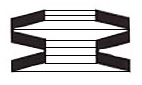
If friction and bottoming-out effects are ignored, the spring rate of a stack of identical Belleville washers can be quickly approximated. Counting from one end of the stack, group by the number of adjacent washers in parallel. For example, in the stack of washers to the right, the grouping is 2-3-1-2, because there is a group of 2 washers in parallel, then a group of 3, then a single washer, then another group of 2.The total spring coefficient is:
- ni = the number of washers in the ith group
- g = the number of groups
- k = the spring constant of one washer
Standards
- DIN 2092 — Disc springs — Calculation
- DIN 2093 — Disc springs - Quality specifications - Dimensions[4]
- DIN 6796 — Conical spring washers for bolted connections[2]
DISC SPRINGS
Introduction:
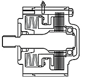
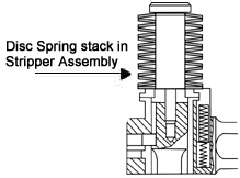
Disc Springs are conically formed angular Discs, which are loaded in the axial direction. Disc Springs offer a well-developed solution to many engineering problems. Through a unique combination of high force in a small space, Disc Springs can be used as single disc or arranged in stacks. A spring stack can consist of either single spring or parallel spring sets. Disc Springs are available with or without contact flats. Disc Springs and Belleville Washers are manufactured to DIN 2093 AND din 6796. We have computerized design programmed to assist our customers for their specified applications. Disc Springs are manufactured from imported 50CrV4 material. Our Disc Springs are AUSTEMPERED. This method of heat treatment is particularly effective for springs, as it gives the maximum toughness and therefore considerable durability.
Advantages of Disc Springs
| 1. | No Deformation or Fatigue under normal loads. | ||
| 2. | High Energy Storage Capacity. | ||
| 3. | Long Service Life. | ||
| 4. | Stock keeping is minimized as the individual spring sizes can be combined universally. | ||
| 5. | Space Saving. | ||
| 6. | Largely Self-damping, giving good shock absorption and energy dissipation. | ||
| 7. | Efficient use of space and high spring force with small deflections. | ||
| 8. | Adaptable to stacking in numerous configurations. | ||
| 9. | Combination use as a modular spring element. | ||
| 10. | Low Maintenance cost | ||
| 11 | Greater Security |
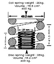
Disc Spring Stack Compared to Helical Spring. | |
| Note that the same load is achieved at substantial reduction in space. Disc stacks may be designed for extremely high loads where coil springs are not feasible at all. |
| |||||||||||||||||||||||||||||||||||||||||||||||||||||||||||||||||||||||||||||||||||||||||||||||||||||||||||||||||||||||||||||||||||||||||||||||||||||||||||||||||||||||||||||||||||||||||||||||||||||||||||||||||||||||||||||||||||||||||||||||||||||||||||||||||||||||||||||||||||||||||||||||||||||||||||||||||||||||||||||||||||||||||||||||||||||||||||||||||||||||||||||||||||||||||||||||||||||||||||||||||||||||||||||||||||||||||||||||||||||||||||||||||||||||||||||||||||||||||||||||||||||||||||||||||||||||||||||||||||||||||||||||||||||||||||||||||||||||||||||||||||||||||||||||||||||||||||||||||||||||||||||||||||||||||||||||||||||||||||||||||||||||||||||||||||||||||||||||||||||||||||||||||||||||||||||||||||||||||||||||||||||||||||||||||||||||||||||||||||||||||||||||||||||||||||||||||||||||||||||||||||||||||||||||||||||||||||||||||||||||||||||||||||||||||||||||||||||||||||||||||||||||||||||||||||||||||||||||||||||||||||||||||||||||||||||||||||||||||||||||||||||||||||||||||||||||||||||||||||||||
DISC SPRING : SYMBOLS & UNITS
![]()
DISC SPRING MATERIALS
DISC SPRING APPLICATION
DISC SPRING INSTALLATION, SETTING & STACKING
| |||||||||||||||||||||||||||||||||||||||||||||||||||||||||||||||||||||||||||||||||||||||||||||||||||||||||||||||||||||||||||||||||||||||||||||||||||||||||||||||||||||||||||||||||||||||||||||||||||||||||||||||||||||||||||||||||||||||||||||||||||||||||||||||||||||||||||||||||||||||||||||||||||||||||||||||||||||||||||||||||||||||||||||||||||||||||||||||||||||||||||||||||||||||||||||||||||||||||||||||||||||||||||||||||||||||||||||||||||||||||||||||||||||||||||||||||||||||||||||||||||||||||||||||||||||||||||||||||||||||||||||||||||||||||||||||||||||||||||||||||||||||||||||||||||||||||||||||||||||||||||||||||||||||||||||||||||||||||||||||||||||||||||||||||||||||||||||||||||||||||||||||||||||||||||||||||||||||||||||||||||||||||||||||||||||||||||||||||||||||||||||||||||||||||||||||||||||||||||||||||||||||||||||||||||||||||||||||||||||||||||||||||||||||||||||||||||||||||||||||||||||||||||||||||||||||||||||||||||||||||||||||||||||||||||||||||||||||||||||||||||||||||||||||||||||||||||||||||||||||
Ball Bearing Disc Springs & Washers (Plain, Slotted and Multi Wave)
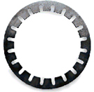
Slotted Ball Bearing Disc Springs
| |||||||||||||||||||||||||||||||||||||||||||||||||||||||||||||||||||||||||||||||||||||||||||||||||||||||||||||||||||||||||||||||||||||||||||||||||||||||||||||||||||||||||||||||||||||||||||||||||||||||||||||||||||||||||||||||||||||||||||||||||||||||||||||||||||||||||||||||||||||||||||||||||||||||||||||||||||||||||||||||||||||||||||||||||||||||||||||||||||||||||||||||||||||||||||||||||||||||||||||||||||||||||||||||||||||||||||||||||||||||||||||||||||||||||||||||||||||||||||||||||||||||||||||||||||||||||||||||||||||||||||||||||||||||||||||||||||||||||||||||||||||||||||||||||||||||||||||||||||||||||||||||||||||||||||||||||||||||||||||||||||||||||||||||||||||||||||||||||||||||||||||||||||||||||||||||||||||||||||||||||||||||||||||||||||||||||||||||||||||||||||||||||||||||||||||||||||||||||||||||||||||||||||||||||||||||||||||||||||||||||||||||||||||||||||||||||||||||||||||||||||||||||||||||||||||||||||||||||||||||||||||||||||||||||||||||||||||||||||||||||||||||||||||||||||||||||||||||||||||||
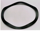
WAVE SPRING WASHERS
| |||||||||||||||||||||||||||||||||||||||||||||||||||||||||||||||||||||||||||||||||||||||||||||||||||||||||||||||||||||||||||||||||||||||||||||||||||||||||||||||||||||||||||||||||||||||||||||||||||||||||||||||||||||||||||||||||||||||||||||||||||||||||||||||||||||||||||||||||||||||||||||||||||||||||||||||||||||||||||||||||||||||||||||||||||||||||||||||||||||||||||||||||||||||||||||||||||||||||||||||||||||||||||||||||||||||||||||||||||||||||||||||||||||||||||||||||||||||||||||||||||||||||||||||||||||||||||||||||||||||||||||||||||||||||||||||||||||||||||||||||||||||||||||||||||||||||||||||||||||||||||||||||||||||||||||||||||||||||||||||||||||||||||||||||||||||||||||||||||||||||||||||||||||||||||||||||||||||||||||||||||||||||||||||||||||||||||||||||||||||||||||||||||||||||||||||||||||||||||||||||||||||||||||||||||||||||||||||||||||||||||||||||||||||||||||||||||||||||||||||||||||||||||||||||||||||||||||||||||||||||||||||||||||||||||||||||||||||||||||||||||||||||||||||||||||||||||||||||||||||
| source: http://www.internationalsprings.com | |||||||||||||||||||||||||||||||||||||||||||||||||||||||||||||||||||||||||||||||||||||||||||||||||||||||||||||||||||||||||||||||||||||||||||||||||||||||||||||||||||||||||||||||||||||||||||||||||||||||||||||||||||||||||||||||||||||||||||||||||||||||||||||||||||||||||||||||||||||||||||||||||||||||||||||||||||||||||||||||||||||||||||||||||||||||||||||||||||||||||||||||||||||||||||||||||||||||||||||||||||||||||||||||||||||||||||||||||||||||||||||||||||||||||||||||||||||||||||||||||||||||||||||||||||||||||||||||||||||||||||||||||||||||||||||||||||||||||||||||||||||||||||||||||||||||||||||||||||||||||||||||||||||||||||||||||||||||||||||||||||||||||||||||||||||||||||||||||||||||||||||||||||||||||||||||||||||||||||||||||||||||||||||||||||||||||||||||||||||||||||||||||||||||||||||||||||||||||||||||||||||||||||||||||||||||||||||||||||||||||||||||||||||||||||||||||||||||||||||||||||||||||||||||||||||||||||||||||||||||||||||||||||||||||||||||||||||||||||||||||||||||||||||||||||||||||||||||||||||||
Langganan:
Postingan (Atom)